Siemens Olb Pspice Download For Linux
OrCAD Capture (Design Entry CIS) is the tool for schematic entry provided by Cadence. Even though OrCAD Capture is provided with a vast variety of libraries for part symbols, sometimes this library may fall short when using a new component. In such a case, we may need to make our own or edit any available part from the library, to use in our given design.To make it easier to follow we have taken a simple Electronic Mosquito Repeller circuit, shown below. This circuit mostly consists of common components such as capacitors, resistors, and transistors; whose symbols can easily be found in the OrCAD library.Now let us suppose we found all the parts in OrCAD library but IC CD4047 wasn’t available in the part library, thus we have to create this part manually. Open OrCAD Capture CIS.
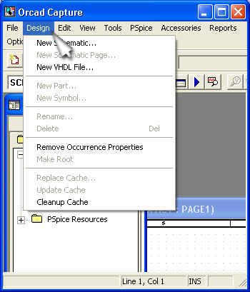
Create a new project named as PARTSYMBOL. The following window appears:In OrCAD, to create our own libraries of part symbols, we have to add a new library to our design. To do this, we will select the.
Partsymbol.dsn in the project window and click File-New-Library. Now right click on the library1.olb file in the project window and select Save As. After naming the library file NEWPART, place it in the project folder in which we are keeping all the design documents. After doing all these steps our project window will look something like this. We will now add parts to our library.Creating SymbolOkay, now to add a new part in our library, right-click on. Newpart.olb and scroll for New Part. This will bring up a dialog box for New Part Properties as shown in figure below.We will fill up the spaces as per requirement while referring datasheet.

In Name enter CD4047, Part Reference Prefix as U, and we will leave PCB Footprint space blank since we haven’t created footprint for this part yet. Other values can be left default as of now. Clicking OK will bring up the workspace for part creation.
As we can see in the figure below, different tools for creating new part are given on the toolbar on the right-hand side of the window.Okay, we have followed the entire procedure which is essential for creating a new symbol, but before creating the symbol lets me mention some points which will be needed for clarity-. Package symbols for components are decided by different international bodies like IEEE, IPC etc. And manufactures uses the same conventions decided by them and we should use only those conventions in our design. Best practice is to use datasheet of the component for getting information like packaging, pins, current rating, size, symbol etc. Here, in this design, for demonstration purpose I am going to create a non-standardized symbol for required IC CD4047 same as it’s given in the circuit diagram.We will now be proceed with part creation for IC CD4047 by using different tools available in the right side of project window. You can alternatively use the Place menu from the menu bar on the top of the window.
Take a listen to Kevin Smith screenplay as he discusses his screenwriting and filmmaking process. The screenplays. Chasing Amy (1997). Chasing amy screenplay pdfs.
First we’ll draw the outline using rectangle tool.Now we will draw the pins of the IC using Place Pin tool. Clicking on this tool will bring up a pop up window and will ask for the different parameters for the pin like Name, Shape, Number and Type. Fill up the spaces as per requirement.
How To Download Orcad For Free
Click OK and place the pin at appropriate places as per component's pin configuration. We can also adjust position and size of the part reference, value, or rectangle we have drawn to an appropriate level. After following all these steps correctly we should have something which looks like the figure below.
Now, save this design and close the window. Our part should be visible in the library.To add this part to your design, open your design’s PAGE1 and click on Add Library or simply press Alt+A. This will bring up a window which will ask for path from which we want to add our library. Give the correct path to the library where you have created the new symbol. If done correctly, the window will show our created symbol and all the information on the right side of it.
Double click on the part name i.e. CD4047 and drag the cursor to schematic page and use the symbol!Next blog in line will explain how you can create the for the symbol you have just created. Created By 2019-10-24 09:04:55 Posted By Ferdinand They turned on their machines, and a current of energy streamed from each machine.

One of the guys yelled that they were to avoid crossing the streams. When asked what would happen if the streams crossed, he stated, would be bad. It is not uncFerdinandThey turned on their machines, and a current of energy streamedfrom each machine.
One of the guys yelled that they were to avoidcrossing the streams. When asked what would happen if the streams crossed, he stated, would be bad.It is not uncommon for a family to incur annual expenses of $50,000 or more for in home care, assisted living, or private nursing home care.The key to finding financial solutions is good planning.More employers are offering company sponsored long term care insurance and mayinclude both employees and for their immediate family members.Cheap Jerseys from china I started small with the salad plates and worked my way upto the dinner ones.